Manual Plunging CryoEM Grids
Single-particle cryogenic electron microscopy (cryoEM) relies upon the imaging of biological samples that have been flash frozen – a process known as vitrification – whereby the molecule of interest is preserved in a “near native” biochemical state in a thin film of “glass-like” ice. Despite numerous advances in the design of transmission electron microscopes, stability of the electron optics, and advances in data collection and data processing strategies, methodologies for vitrifying biological samples for cryoEM have changed little since originally created over 40 years ago, with many aspects of this technique, including the equipment that have been developed for this process, rely on the originally described “blot-and-plunge” method. Briefly, a small volume of sample (i.e., 3 µL) is applied directly to the hydrophilic surface of a specialized EM grid (of which there are many types) and excess sample solution is removed using physical interaction between blotting paper and the EM grid before the grid is quickly plunged into liquid ethane maintained at liquid nitrogen temperature. The combination of the thin layer of sample and the high rate of heat transfer in the liquid ethane prevents water molecules from forming crystalline ice, resulting instead in a vitrified layer of liquid with the molecules of interest randomly distributed in it.
This process represents an integral component of the cryoEM workflow and is necessary to render specimens suitable for imaging in the vacuum of the electron microscope. Importantly, a critical aspect of preparing cryoEM grids is the resulting thickness of the vitreous ice film in which the particles are embedded. Specifically, when the ice is too thick (i.e., >1000 Å) then imaging quality decreases noticeably due to increased scattering of the electron beam by the surrounding ice. In contrast, ice that is too thin can constrain protein orientations, often preventing particles from locating to the center of the grid foil holes which can severely hinder successful structure determination. The timing of the blotting process controls the thickness of the thin film but, unfortunately, this exact timing is usually empirically determined for each specimen, often through trial and error, and without guaranteed success as sample properties and buffer conditions can alter the behavior during blotting. This dependence on obtaining the optimal ice thickness for single-particle cryoEM imaging has guided the development of many equipment that can freeze samples (i.e., robotics, microfluidics, and ultrasonic devices or spraying devices). Most of the advances in sample preparation since vitrification was introduced have centered around automating the process. While the first implementation involved a simple manual plunger, typically used in a cold room to control temperature and humidity, modern devices (e.g., the ThermoFisher Vitrobot Mark IV, the Gatan Cryoplunge 3, and the Leica EM GP2) are computer-controlled, have enclosed chambers with temperature and humidity control, and have automated most of the process.
The most popular cryoEM grid preparation devices rely upon robotics to automate the vitrification of samples using the blot-and-plunge technique, however, the fundamentals of the steps involved – sample application, blotting, and plunge-freezing – have remained unchanged. While these devices were designed to reproducibly prepare grids with optimal ice thickness for imaging, this is not guaranteed and often the resulting EM grids possess considerable variability in ice thickness and particle quality. Furthermore, these robotic blotting devices are often too expensive for individual labs to purchase and operate, with many locating to cryoEM facilities with hourly rates for usage. Recently, the original manual “blot-and-plunge” technique has reemerged as a viable option whereby a skilled researcher can achieve the same, if not better reproducibility as the robotics mentioned above, at a fraction of the cost, and can easily be owned and operated by individual labs. In addition, manual blotting offers users more control over the blotting process as researchers can easily adjust the blotting mechanism and blotting time based on sample type (e.g., soluble proteins, integral membrane proteins, filaments, cells, tissues, etc.) and research questions. Here, we describe the development and implementation of the Mark V, a cheap and versatile manual plunging platform that allows for the rapid and reproducible freezing of biological specimens using a traditional “blot-and-plunge” style plunger. Each of these components can be easily sourced at low cost and many components can be 3D printed using widely available resources.
Manual “Blot-and-plunge” cryoEM grid preparation device
The manual plunger (Figure 1) consists of multiple simple components: the plunging arm; grid clamping tweezers, which are held in place with tape; a stand to hold the plunging arm in place with the bar clamp; a pedal cable attached to a foot pedal that releases the bar clamp by pulling on the cable when pressed; a bump stop that stops the plunging arm and thus establishes the tweezers at a set working height; a dewar clamp that holds the blue Styrofoam dewar (Spear Lab FD-500) in place for plunge freezing; and the dewar platform for the ethane cryogen and grid storage.
Importantly, the manual plunger has minimal moving parts that do not require continuous and costly maintenance and our new Mark V dewar platform design provides the user more control over the grid freezing process by providing quick access to the EM grids, effortless adjustment of blot time and easy preparation of the ethane (or ethane:propane) cryogen. This simple design can be easily 3D printed using readily available resources and allows for future customization depending on the needs of the end user. Many of the components were designed in a 3D modeling software, 3D printed at a low cost, and used and operated nearly free of charge. The Mark V manual plunger provides reproducible grid freezing results at both low upfront cost and minimal maintenance and serves as an easily accessible alternative to robotic blotters.
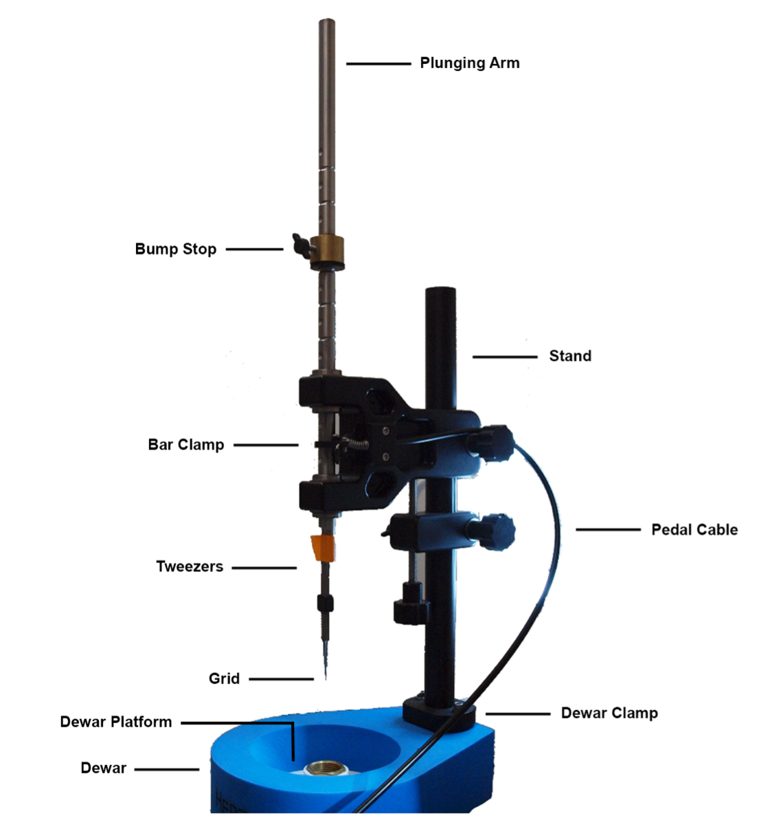
Figure 1 Traditional “blot-and-plunge” style manual plunger. Diagram showing the manual plunger setup with the Mark V. The bump stop sets the working height of the tweezers. The pedal pulls on the cable and releases the bar to the working plunge height. The attached tweezers hold the grid during plunging and vitrification.
Platform Design
The dewar platform was designed with ease of use and setup, taking into consideration the price of each component and accessibility, while also providing the end-user the ability to modify the design to tailor their specific needs. Each component of the dewar platform was designed using a simple CAD program (eMachineShop, Mahwah, NJ) and the additional holes were added using the free 3D modeling software Blender (version 2.91.2, Amsterdam, Netherlands). Importantly, each component of the dewar platform can be 3D printed at a low cost using easily sourced materials (see below).
There are two designs for the dewar platform: one configuration (Figure 2, left panel) is designed to be used with liquid ethane while the second design (Figure 2, right panel) is similar in nature but modified for use with a 50:50 ethane:propane mix. Specifically, six holes were added to the wall of the ethane vessel holder to allow for the liquid nitrogen that is poured into the dewar platform will remain in contact with the brass ethane vessel to ensure adequate cooling of the ethan:propane mixture. Once the brass vessel is sufficiently cold, the liquid ethane begins to solidify (Figure 3, left). The ethane should not be allowed to completely solidify, however, in the brass vessel and sufficient liquid ethane must remain in the center of the brass vessel so as to not damage the grids during plunging.
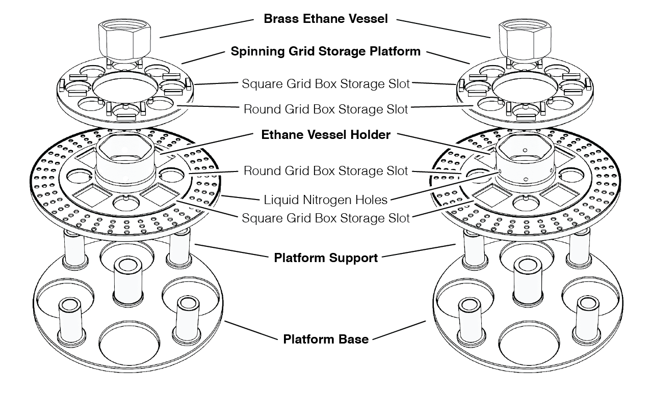
Figure 2 Mark V dewar platform design. Schematic diagram of the Mark V plunge freezing dewar detailing critical components. The platform base establishes the height of the dewar platform. The Platform Support rests on the Platform Base and houses the Brass Ethane Vessel. The Spinning Grid Storage Platform houses grid boxes for the storage of EM grids that have been prepared and flash frozen. Shown on the left is a design for the use of ethane cryogen and the design on the right, with holes engineered in the Ethane Vessel Holder, is designed to work with a ethane:propane (50:50) mix.
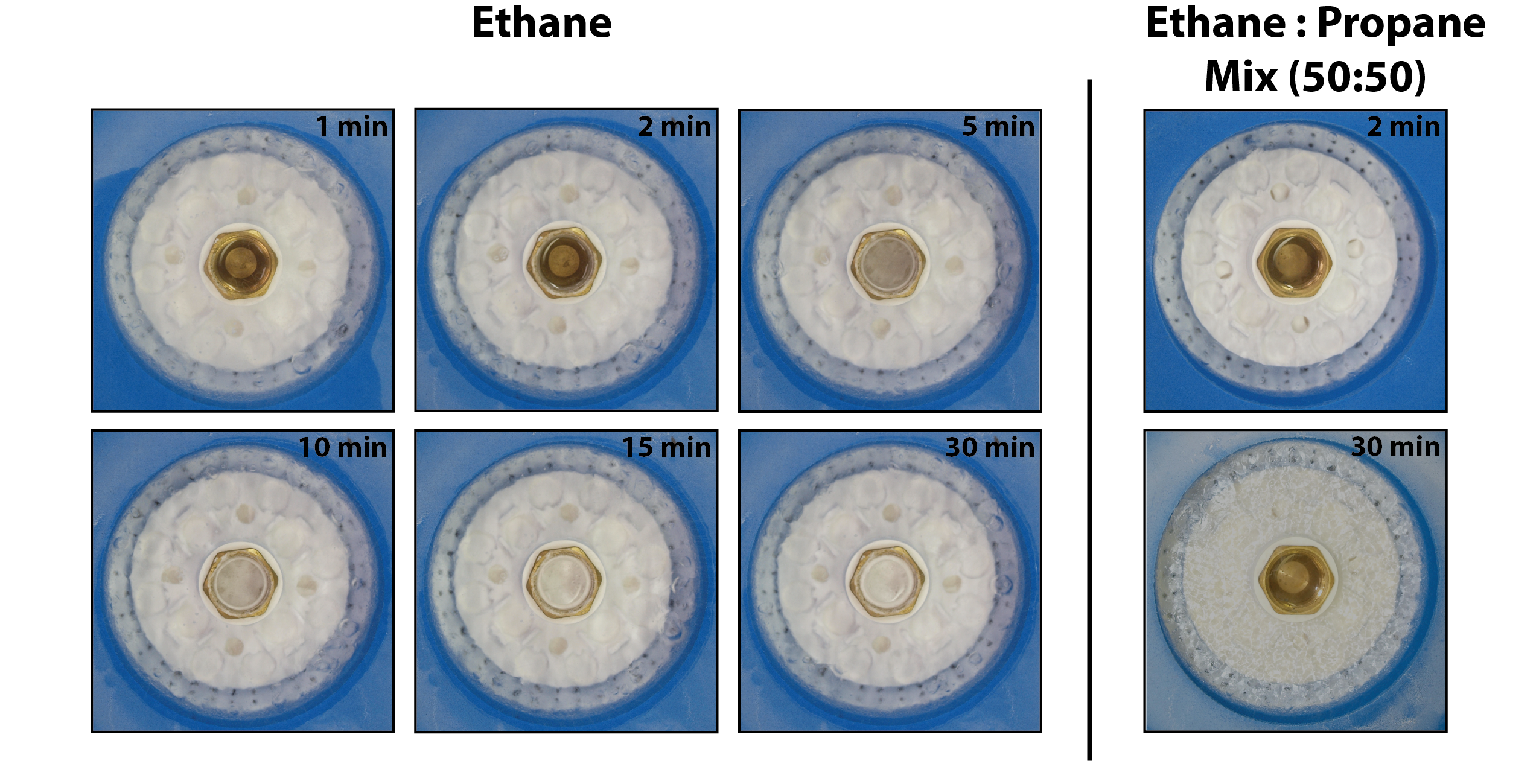
Figure 3 Cryogen preparation and stability. Timelapse of liquid ethane solidifying over 30 minutes (left panel) before primed for grid freezing. By contrast a 50:50 ethane:propane mix (right panel) remaining in liquid state over the 30 minutes, but primed for grid freezing immediately.